During the last years, three-dimensional scanning technologies have evolved rapidly. Several digitizing systems have been proposed which can be divided into two main categories: contact systems and non-contact systems.
The contact systems digitize a surface by means of a mechanical digitizer, so that the acquisition time may be extremely long.
The evolution of optical sensors and optical devices allowed to development of a new optical non-contact techniques.
These methods, which may dramatically reduce the acquisition time, are divided in passive and active techniques.
Passive techniques do not require any additional energy source, while active techniques require an auxiliary light source. These systems are commonly used in orthodontics to create Computer-Aided-Design (CAD) models of the dental arch.
Nowadays, most dentists approach the process of dental arch shape detection using a classic procedure, which consists, at first, in the use of an impression material to detect the shape of the patient’s dental arch and, subsequently, in the creation of a dental cast from the impression by means of dental stone.
As a further step, the dental cast may be digitalized using different shape acquisition methods to obtain a suitable virtual model.
For many years researches have been trying to improve this conventional process to minimize the acquisition time and to optimize the final result, i.e., the CAD model.
The initial studies were concerned with the use of intraoral probes, operating either by means of a laser triangulation technique [3], or by a digitalized projection pattern.
The main disadvantages are the following:
(a) the probe’s mechanical components are not sterilizable and (b) the probe itself must be replaced frequently, thus affecting the overall cost of the procedure. In recent years, many studies were focused on the development of new devices to reduce the production costs and to automate the whole scanning
process [5].
Given the limited success of these procedures, as a result, nowadays, dentists are provided with specific mechanical or optical digitizers of different types, which are able to scan the stone dental arch and produce a virtual model of it.
In particular, some devices use topometric methods or laser beam/structured light methods [6] to scan a dental stone and obtain a CAD model of dental arch.
To improve the data acquisition process, new optical devices were developed, as for instance, the Charside Economical Restoration of Esthetic Ceramics (CEREC) [8] or the 3MTM system [9].
The camera is moved manually in the patient’s mouth by the dentist.
Being the scanning process sensible to patient’s movement, in the case of absence of such movements the measurement accuracy in depth reaches up to 19 μm.
With few exceptions, all these mechanical and optical devices have hence a relatively high precision.
On the other hand some devices may be only used to scan the dental stone; some others, as the intraoral digital device, are sensitive to small movements of patient that could compromise the quality of the final result.
Currently, as far as the authors are aware, no device is able to automate the scanning process and eliminate the manual scanning. This would dramatically reduce the errors during the data acquisition process and eliminate the impression phase and the use of the stone model.
This paper is concerned with the development of a novel non-contact scanning system, which allows obtaining the CAD model of the dental arch without the use of an impression material, and thus directly from the patient’s mouth. This optical system, which uses a structured light source and an optical sensor to acquire images, is based both on the coded light technique and the epipolar geometry principle.
|
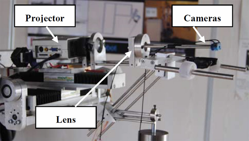
Fig. 1 Optical system. |
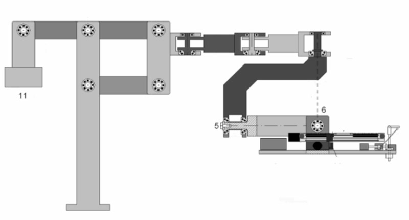
Fig. 2 Scheme of the self-balanced arm. |
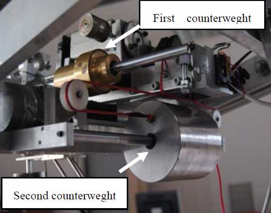
Fig. 3 Sliding counterweights. |
|
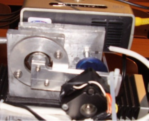
Fig. 4 Mechanism to tilt laterally the detecting device. |
Fig. 5 Photo of the system used to block the patient. |
Fig. 6 Dental scanner. |
This system allows the suppression of five steps in the classic procedure:
1. the material application;
2. the material hardening;
3. sending the impression;
4. casting the model;
5. scanning it.
After obtaining the CAD model of the dental arch, a new system to guide the doctor in the placement of the fittings in the oral cavity is needed.
Presently dental prosthesization using implants requires long times between implant positioning and prosthesis fitting, beside the problem of correctly positioning of the implant where enough bone stock exists, and with the correct inclination to support the load of mastication.
It is in fact necessary first to detect the shape of the dental arch, then generate a plaster model, which is to be scanned. On the base of this and of a Computet Axial Tomography (CAT) or an orthopantomography the doctor decides the optimal position of the implants and proceeds manually.
Only alternative to free hand positioning, the use of Nobel Guide masks [10].
In this case first the doctor, navigating through the CAT virtual representation of the patient’s mouth, establishes where to place the implants taking into account the amount of bone stock available.
Then these information are sent to Nobel Guide, which returns the mask which presents guiding holes where the implants are to be positioned.
This paper describes also an implant positioning 2 + 1 degree of freedom (DOF) robotic system, which should be combined with the 3D scanner, to guide the doctor in the placement of the fittings in the oral cavity, according to what previously decided from the exam ofa CAT representation of the patient mouth.
The paper is organized as follows: Section 2 discusses the scanning system; section 3 introduces the theory of camera and projector calibration; section 4 is about the calibration results; section 5 introduces the implant position; section 6 gives conclusions.
The Scanning System
The aim of this research is to develop an innovative optical scanner which, using a particular coded light technique, allows to obtain the CAD model of the dental arch directly.
The optical section of the scanner, as shown in Fig. 1, is composed by a mini-projector with a resolution of 800 × 600 pixels, two micro-cameras with a resolution of 352 × 288 pixels and a biconvex lens.
This part of the scanner is located on a planar moving system which is actuated by two step motors via linear sliders. The step motors are controlled by a microcontroller, which allows to perform the automatic handling of the linear sliders and to memorize the teeth positions. Projector, lens and cameras locations are fixed to each other, but movable with respect to the denture to be examined, through a micrometric position control.
A tilting mechanism of the entire optical system is present and a mirror’s angular control will shortly be added as well, in order to improve the detection ability of this system. A six degree-of-freedom (DOF) self-balanced arm, whose scheme is shown in Fig. 2, supports the whole system. As can be noted in the figure, the plate on which the system rests is suspended to the point in which at least the last two rotational axes (5 and 6) meet. The weight of the entire system is balanced by a counterweight, (11) in the figure.
Thus, in order to avoid any disturbance to the patient, the center of mass of whatever is placed on the plate must coincide with the point of intersection between the two last axes. But since the slides are present, than two suitable sliding counterweights are also present, driven by the motion of the slides, but in opposite Fig. 1 Optical system. Fig. 2 Scheme of the self-balanced arm. direction.
This detail is shown in the picture (Fig. 3). Note also that this arrangement allows rotating the entire plate by 180° when the upper dental arch is to be examined. The projector, lens and cameras system can also be tilted in order to detect correctly the collar area of the molars, and this is controlled rotating a small cam (the blue element in Fig. 4).
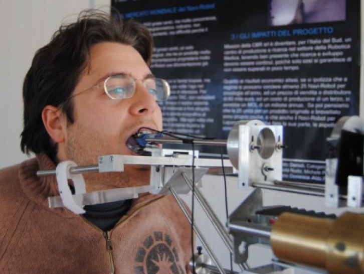
The scanning system is kept in fixed position with respect to the patient’s head through a suitable mask resting on the vestibular area, fixed to a U shaped external structure, secured with straps to a second external structure pressing the chin (Fig. 5).
The mask provides a support for the miniaturized detection system of the teeth shape. This latter can be moved in a x-y plane within the oral cavity, allowing the identification of the teeth position in terms of their coordinates.
There are two phases of the process: during the first phase the doctor, once positioned the mask in the patient’s mouth, drives the system along the teeth to be scanned, observing them through the cameras, so that the device records the trajectory imposed by the doctor.
Fig. 3 Sliding counterweights. Fig. 4 Mechanism to tilt laterally the detecting device. Fig. 5 Photo of the system used to block the patient. In the second phase the control algorithm give the signals needed to allow the intra-oral feature to enter the patient’s mouth and move according to the trajectory previously selected by the doctor.
To allow these movements, the microcontroller calculates the optimal number of steps the motor has to rotate and the direction of rotation. During motion, the actual location is monitored by the sensors and once the selected location is achieved, its coordinates are memorized in order to be post-processed by the software during reconstruction.
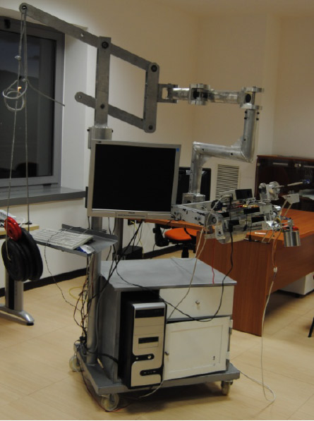
Finally, Fig. 6 shows the entire dental scanner. Fig. 6 Dental scanner.
Theoretical Analysis of Calibration Method
In this work a new algorithm to obtain the dental arch CAD model is developed.
The method consists in the calibration of the optical scanner and in the subsequent scanning of the dental arch by means of structured light, whereas a particular calibration procedure is used to calculate the intrinsic parameters of the projector.
This technique needs a mini-projector, two micro-cameras b/n and two planar chessboard with known size (Figs. 7a-7b). The micro-cameras have to acquire two image sets to obtain the calibration parameters.
The camera calibration parameters are used for the projector calibration. Once the camera calibration parameters and projector calibration parameters are obtained, the optical scanner with the active triangulation method is calibrated.
The full calibration process is composed by three steps:
(1) Camera calibration;
(2) Projector calibration;
(3) Scanner calibration.
[……] For consult full article, click to the link down.
Authors’ Contributions
Paola Nudo(1), Michele Perrelli(1), Mario Donnici(1), Guido Danieli(1), Francesco Inchingolo(2), Francesco Giuzio(3) and Massimo Marrelli(4)
1. Department of Mechanic, Engineering, University of Calabria, Arcavacata Rende 87036, Italy
2. Department of Dentistry, Faculty of Medicine, University of Bari, Bari 70100, Italy
3. Doctor’s Office, Cosenza 87100, Italy
4. Dentalia S.r.L, Crotone 88900, Italy Received: September 09, 2011 / Accepted: September 29, 2011 / Published: October 25, 2011.
References
[1] T. Varady, R.R. Martin, J. Cox, Reverse engineering of geometric models—an introduction, Computer Aided Design 29 (1997) 255-268.
[2] S.M. Yamany, A.A. Farag, D. Tasman, A.G. Farman, A 3-D reconstruction system for the human jaw using a sequence of optical images, IEEE Transaction on Medical Imaging 19 (5) (2000) 538-547.
[3] F. Duret, J. Blouin, Process and apparatus for taking a medical cast, US Patent Nr. 4952149, 1990.
[4] R. Massen, J. Gassler, Optical probe and method for the three-dimensional surveying of teeth, US Patent Nr. 5372502, 1994.
[5] S. Witkowski, (CAD-)/CAM in dental technology, Quintessence Dent Technol 28 (2005) 169-184.
[6] I.A. Pretty, G. Maupomè, A closer look at diagnosis in clinical dental practice: Part 5. Emerging technologies for caries detection and diagnosis, Journal of the Canadian Dental Association 70 (8) (2004) 540a-540i.
[7] G. Arnetzl, D. Pongratz, Milling precision and fitting accuracy of Cerec Scan milled restorations, International Journal of Computerized Dentistry 8 (4) (2005) 273-281.
[8] W.H. Mörmann, The origin of the Cerec method: a personal review of the first 5 years, Int. J. Comput. Dent. 7 (1) (2004) 11-24.
[9] D. Suttor, K. Bunke, S. Hoescheler, H. Hauptmann, G. Hertlein, LAVA—the system for all-ceramic ZrO2 crown and bridge frameworks, Int. J. Comput. Dent. 4 (3) (2001) 195-206.
[10] G. Orentlicher, M. Teich, Evolving implant design. The nobelactive implant: discussion and case presentations, Compendium of Continuing Education in Dentistry 31 (1) Dental Arch3D Direct Detection System from the Patient’s Mouth and Robot for Implant Positioning 341 (2010) 66-70, 72-77.
[11] Z. Zhang, A flexible new technique for camera calibration, IEEE Transactions on Pattern Analysis and Machine Intelligence 22 (11) (2000) 1330-1334.
[12] R. Tsai, A versatile camera calibration technique for high-accuracy 3D machine vision metrology using off-the-shelf TV cameras and lenses, IEEE Journal of Robotics and Automation 3 (4) (1987) 323-344
[13] J. Weng, P. Cohen, H. Marc, Camera calibration with distortion models and accuracy evaluation, IEEE Transaction on Pattern Analysis and Machine Intelligence 14 (1992) 965-980.
[14] L. Chen, C.W. Armstrong, D.D. Raftopoulos, An investigation on the accuracy of three-dimensional space reconstruction using the direct linear transformation technique, J. Biomech 27 (1994) 493-500.
[15] H. Hatze, High-precision three-dimensional photogrammetric calibration and object space reconstruction using a modified DLT-approach, J. Biomech 21 (1988) 533-538.
[16] J. Guhring, C. Brenner, J. Bohm, D. Fritsch, Data processing and calibration of a cross-pattern stripe projector, in: Proceedings of IAPRS Congress, Vol. 33, 2000, pp. 327-338.
[17] M. Trobina, Error model of a coded-light range sensor, Technical Report BIWI-TR-164, ETH Zentrum, 1885.
[18] M. Kimura, M. Mochimaru, T. Kanade, Projector calibration using arbitrary planes and calibrated camera, in: IEEE Conference on Computer Vision and Pattern Recognition (CVPR’07), Minneapolis, June 17-22, 2007.